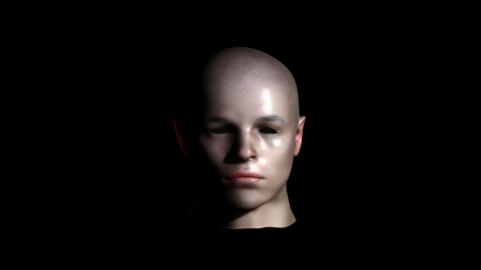
Rendering Skin With Mental ray.
In 3dsmax the default render option is Scanline. To change this to mental ray; go to the Render Setup > Assign Renderer > Choose Renderer > mental ray.
There are four Subsurface Scattering materials within mental ray: –
- SSS Fast material
- SSS Fast Skin material
- SSS Fast Skin material plus Displacement
- SSS Physical material
The first three are described as non-physical shaders and the fourth described as physical.(Livny, 2008 pp633-678) This last shader is used for single layered material such as jade, milk, soap, wax etc. and calculates accurate renders of these materials. Physical shaders are difficult to set up and are not used for skin rendering. (Livny,2008 pp679)
The first three however are used for multi-layered materials such as skin, where physical accuracy is not required (van der Steen 2007 pp176-177) The parameters are set out in an easy to use roll-out, with all the layers listed together for manipulating. (Figure. 1 .) The user can adjust the parameters to suit the overall outcome of the final render and need not be tied to realistic computations and so has a larger scope for creativity.
Fig. 1.
SSS Fast skin will be used as the shader from mental ray, to render the subject, as it is the basic shader that mental ray uses during the process of creating skin . Using SSS Fast Skin plus Displacement removes some of the controls from the user, adding displacement by default. A displacement map can be added later if needed, while SSS Fast material on its own does not give parameters for epidermal and sub-dermal scattering, two important factors in skin rendering.
SSS shaders use real world units to scatter light. There is a Scale Conversion Factor in the SSS Fast Skin rollout. If the model is to small, when the SSS Fast Skin is applied, then light will scatter through it too much giving it a plastic appearance. (Figure.2.) If the scale is too large then the scattering will not visually affect the model and give it a stone or clay appearance. (Figure.3.)
Fig.2. Here the Scale Conversion Factor is set at 0.1.
Fig.3. Here the Scale Conversion Factor is set at 2.
Fig.4. Here the Scale Conversion Factor is set at 1.
In Figure.4, the Scale Conversion Factor is set at 1by default. In this case, this setting appears to be correct judging by observations of backscattered light penetrating through the right ear.
When an inverted gray-scale map (Figure.5.) is added to the bump shader (Figure.6) and the Specular weight is reduced from default 0.3 to 0 the
 Fig.5.
Fig.6
Fig.7. Specular Weight #1 set to 0. and bump map set at 0.05
.
Fig.8. Overall Specular Weight set at 0.4
Fig.9. Lighting from both sides and rear.
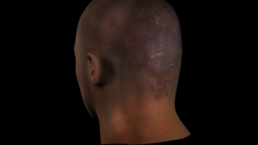
Fig.10. Back of subjects head.
That Seam is still there!!! GDI!
Fig.11. The individual maps used in the creation process.


